Assembly time 1-2 hours
INVENTORY:
- 1 Master 24v tile
- 1 Rabbit Ethernet Controller
- 8 24v Standard tiles
- 24v 400w AC to DC power supply.
- card with replacement LEDs, stickers
- 3mm allen tool
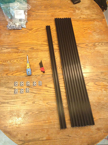
for building the frame
- 2 shorter v-rail extruded aluminum bars
- 8 longer v-rail extruded aluminum bars
- 16 corner brackets
- 32 Zinc plated m5 bolts (10mm phillips)
- 32 t-nuts
- 20 lock washers
for mounting the tiles
- 36 black hex m5 bolts (10mm)
- 36 spacer washers
- 36 wide washers
- 36 t-nuts
cables
- Power harness with 9 XT60 connectors
- wall cord for power supply
- 6 short iec cables
- 1 medium iec cable
- 1 long iec cable
What you need:
- Phillips Screwdriver
- Wifi router
- Ethernet cable
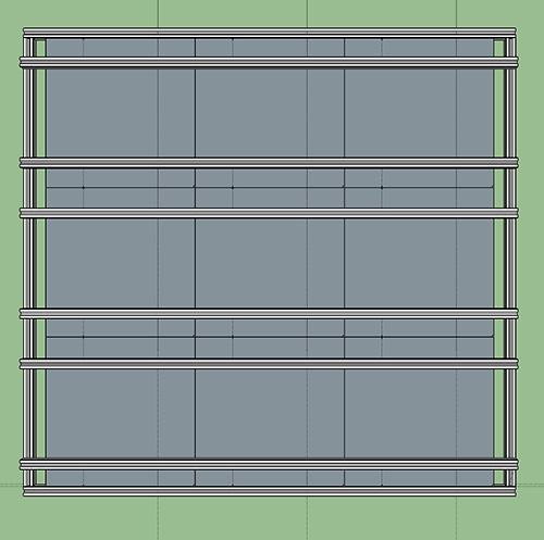
ASSEMBLY – download a sketchup model
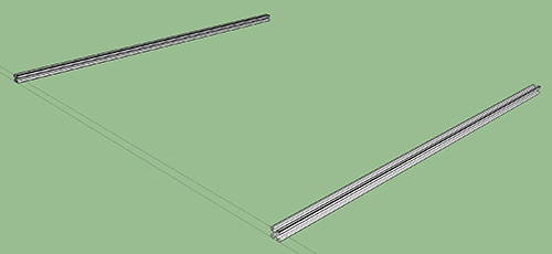
1) Find two v-rail bars that are shorter than the other 6.
These are the left and right vertical bars, all the longer ones will be horizontal
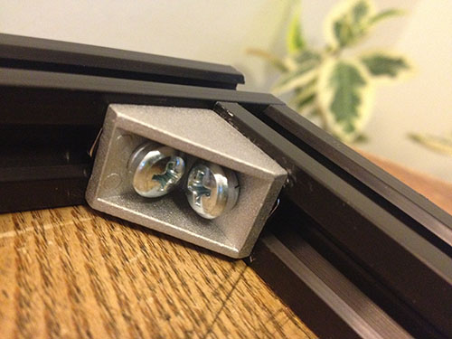
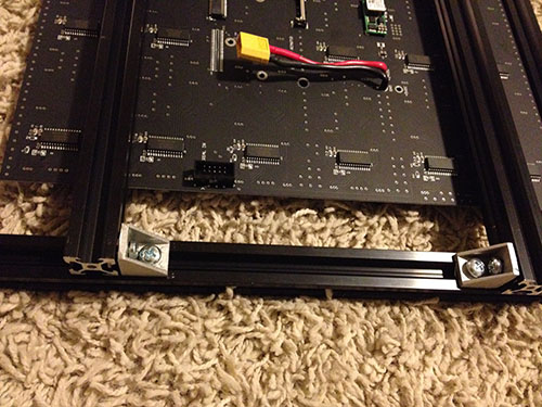
2) Slide 6 right angle brackets onto each of the short bars.

These will connect to the back crossbars later. The direction does not matter yet because they can rotate once slid into the slot.
Each angle uses 2 t-nuts, 2 silver philips bolts and 1 lock washer. *Note* The reason that only one bolt gets a lock washer is because there are bumps on the bottom of the bracket that align it with the slot in the aluminum. When the bracket is rotated, these bumps don’t fit in the slot and therefore the bolt is too short to fit a lock washer.
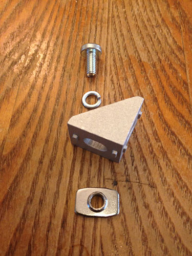
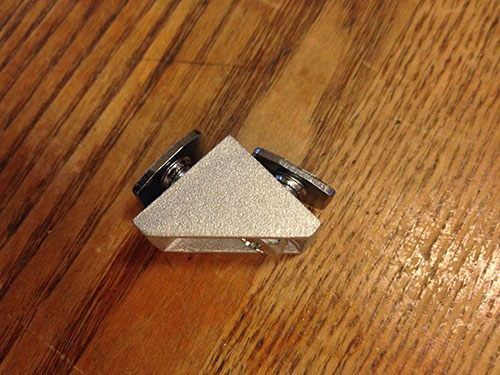
The pan head bolts are a tight fit, so its best to pre-thread them with the lock washer, then bracket and the t nut on the back. The lock washer goes between the pan head and the bracket. Now slide each one into the bar using the side with the lock washer on it.
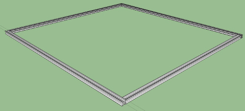
3) Make the basic square by adding longer bars to the top and bottom.
Again, its easiest if you pre-tread the brackets with lock washers and t-nuts, then slide them in. This time both sides get a lock washer. Because the aluminum is a bit flexible, you can slide in the 4th corner. First get all the bolts snug. Then when the alignment is right, you can crank them tight.
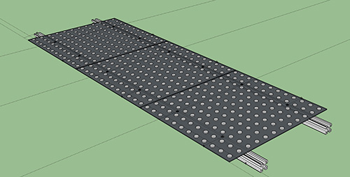
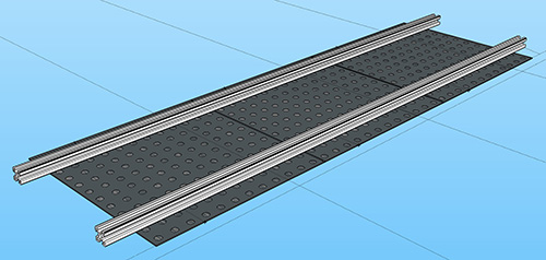
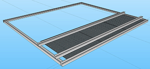
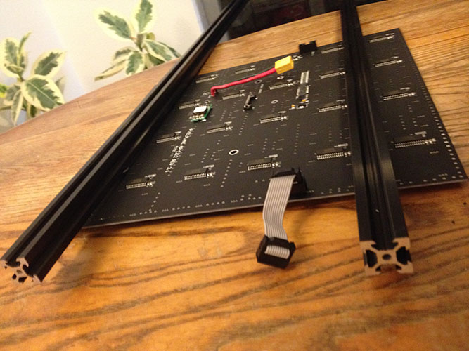
4) Mount the first 3 tiles.
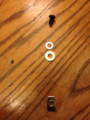
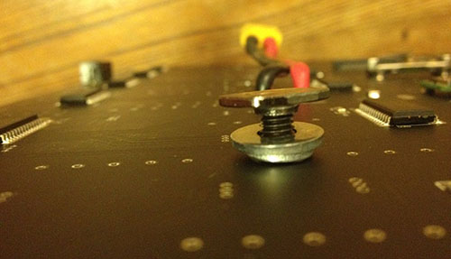
The best way to do this is to pre-thread all the hardware for the tiles, place them in a line face down, then slide the bar onto the t-nuts. *Note* There are 2 sizes of washers, the small one goes against the tile. This acts as a spacer to prevent any short-circuits between the frame and the tile. The bigger washer ensures that the tile mounts flat against the v-rail which is beveled. The order is:
- black bolt
- tile
- small washer
- big washer
- t-nut
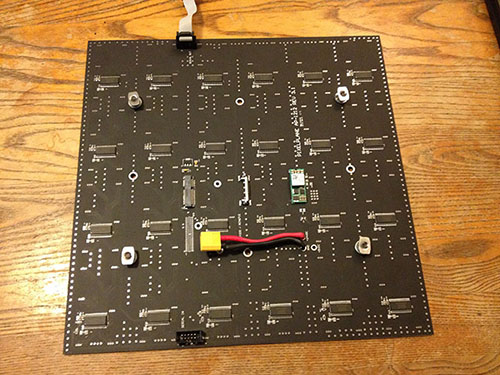
Prepare the hardware using the four mounting holes at the corners of the square. Do this for 3 tiles. Start with the MASTER tile at one end and add 2 more. Now line them up so that the text is facing the same direction. *Important* the bars will be parallel to the text “AP 1212 REV3.1”. Now you can slide the bar on to the t-nuts. The bar will go between the t-nut and the large washer. This step may be the most tricky, but be gentle and you will get it on there!
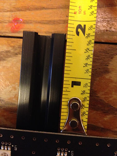
Leave 1 and 3/4 inches of bar hanging off both edges, the tiles should be touching each other.
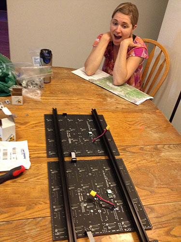
5) Make 2 more sets of 3.
Repeat step 4 with the rest of the tiles. You will end up with 3 sets of 3, with one having the Master tile.
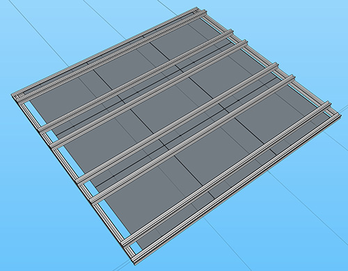
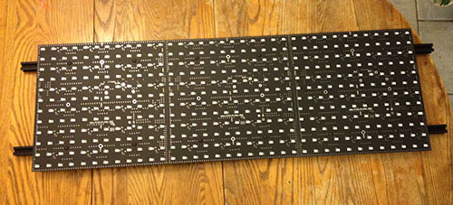
6) Mount the sets of 3 to the back of the square frame.
Start with the set that contains your Master tile. Place this face-down on the square frame so that the Master is in the corner. This will be your bottom row. Now connect the brackets that you slid onto the square frame earlier to the cross bars. The brackets can be on the inside or outside of the cross bars. They can all face the same way or alternate, this is your choice. You can slide onto the t-nuts that have NO lockwashers that you set up in step 2.
7) The middle row of tiles is upside down.
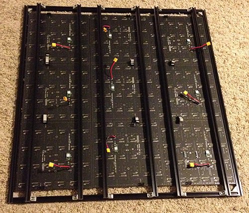
The serial chain will make an S pattern through the 9 tiles. So the middle row is oriented 180 degrees from the top and bottom rows. Again just get the bolts snug until you have it nicely aligned. Then tighten everything down at once.
8) Wire it up. The power harness cable will also make an S shape as it connects all the tiles together. The last tile (farthest from the master) should be the tip of the power wire. This way you have power and data both originating at the master tile. The short serial (iec) cables jumper between tiles that touch, the medium and log connect one row of tiles to the next.
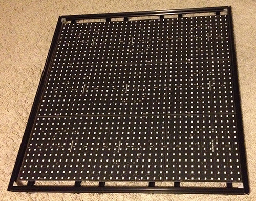
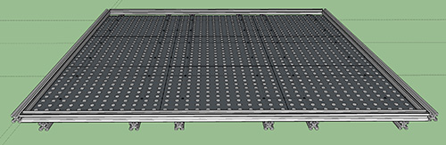
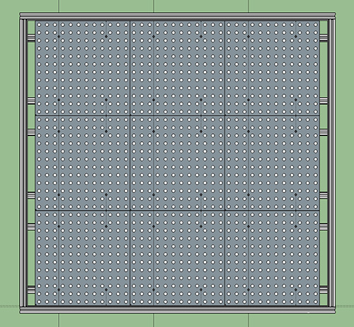
3D view: